🧱 WALL BUILDER — BUILT ON THE PLAN (OCT 27)
No photo stretched under this one — the whole wall is built on the plan: the full 7′-8″ run, face to face — grid C to grid D measures 8′-8″ on A102. Steel comes off the structural set. A service is drawn only where a photo or a plan actually shows it — if it hasn't been seen, it isn't on here, and the bottom notes name what's known but not plotted. The scan still runs before any cut.
🧱 WALL BUILDER — PPE / DECON WALL
Wall X-Ray · the wall between PPE 113 and Decon 114 — 8″ CMU, 7′-8″ long face to face (8′-8″ grid C to grid D), 14′-0″ tall. The plan puts the whole wall in front of you; drag the 12″×12″ opening along it and it tells you what you would hit.
The whole wall on the plan — tap a room to see that face's photo
The two faces — Art's photos, Oct 27
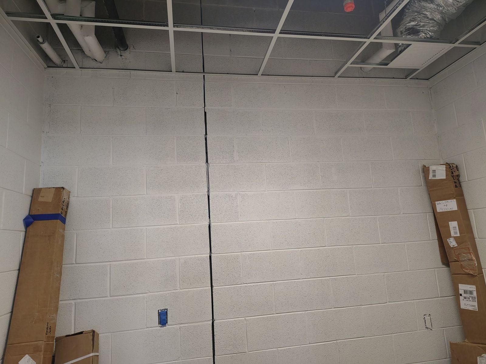
PPE ROOM SIDE. Painted block, floor to the 9′-6″ ceiling. The control-joint groove runs floor to ceiling at mid-wall (your phone saved this picture sideways — it's shown turned right). Seen on this face: a device with a blue plate ≈1′-3″ off the floor on the photo-left half, a blank device outline ≈1′-3″ near the photo-right end, boxes resting at the floor. The storefront past the photo-right corner is the next wall over — not this wall.
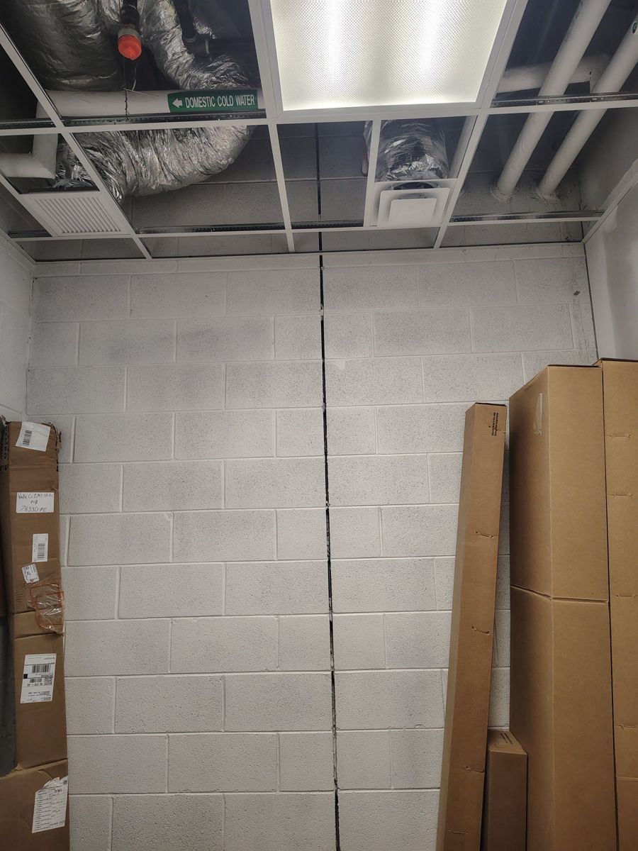
BACK OF PPE ROOM — the Decon side. The control-joint groove stands vertical at mid-wall here too. Open ceiling: a domestic cold water pipe + ducts run above the ceiling line — in the plenum in front of the wall, not in the wall. This photo starts at ≈2′-3″ off the floor (the floor is out of frame) and runs to ≈11′-0″.
The wall, built — drag the opening
…
CL from control joint
—
CL height
—
Top of opening
—
From photo-left end
—
Layers — tap to show / hide
HOW THIS ONE IS BUILT: the base is the plan — A101/A111 — with the whole wall run in context (Decon 114 on one face, PPE 113 on the other; bay-side wall at grid C on one end, exterior wall at grid D on the other). The wall below the plan is that same run stood up: block courses at 8″, the control joint drawn as a joint line at mid-length with the solid poured cells beside it in light shade only, steel off S101/S102/S103/S201/S303. The wall build's left/right follows the PPE photo (photo-left / photo-right) — which photo end is the bay side isn't confirmed, and it doesn't change a verdict: the steel pattern is symmetric about the joint.
WHAT'S VERIFIED FOR THIS WALL (plans): S101 puts a masonry control joint (WCJ) at the mid-length of this wall — and the groove is visible on both faces in Art's Oct 27 photos. Per 4/S303 the first cell each side of the joint holds a vertical #5 and is grouted solid (CJ ±8″). Per S102/S103 Note 1, #5 verticals @ 24″ o.c. full height, with bars at the wall ends — so bars sit at ±2′ and at the wall ends, measured from the joint (the 7′-8″ run is too short for a ±4′ bar). Top of wall: bond beam 12′-8″ to 14′-0″, (2) #5 (S201). A101 draws no door in this wall and no fixtures on either face — Decon's shower unit is on Decon's Mech-side wall; Decon's and PPE's doors are in the bay-side wall beside this one. Ceilings: 9′-6″ both rooms (A111 — field-confirmed by Art, Oct 27).
SEEN — AND DRAWN WHERE IT WAS SEEN: PPE face — the blue-plate device and the blank device outline, both ≈1′-3″ AFF (photo). Decon side — domestic cold water pipe + ducts above the ceiling (photo) — plenum, not in the wall, drawn above the ceiling line. At the grid D corner — two gray EMT stubs in the exterior wall right at this wall's junction (steel-era photo, foundation-rebar ev-09) — marked on the plan above, at the corner where they were seen. On the plans — E101 puts receptacles on this wall: both faces at the bay (grid C) end and one on the PPE face near the joint; they're drawn at their plan spots (symbol positions, approximate) because a device on the face means a box in the wall. On the plans — P201 / P200 / E201 show crossings IN this wall: 1″ cold + 1″ hot mains at the north end and a ½″ hot at mid-plan (P201), a 1½″ vent in the south half and MS-1/FS-1 back-to-back at the south end (P200), a GFI receptacle on the Decon face ≈40% from the north end (E201) — and M200/M201 show the 12″×12″ exhaust trunk crossing above the ceiling at the south end. The in-wall crossings are plotted on the wall below as PLAN-SHOWN station bands; no height is dimensioned for any of them, so no height is drawn.
IN THIS WALL — NAMED BY ART, NOT PLOTTED: COPPER pipe and CONDUIT (pipes for wires) are in this wall — Art's word, Oct 27. No photo and no plan pins their runs inside this wall, so the runs are not drawn. They are exactly what the pre-cut scan is for, and every CLEAR verdict on this page says so. What the plans DO pin is plotted: P201 crosses this wall with the 1″ cold + 1″ hot copper pair at the north end and a ½″ hot at mid-plan (valve CBV 1GPM) — station only, no height dimensioned. (The pair of blue lines in the Mech-room photos is the air-conditioning control conduit on the Mech/Decon wall — E001 legend, Art's ID. Not this wall.)
NOT PLACED — NOT SEEN: no in-wall sprinkler is placed in this wall — FP200 shows no sprinkler pipe in or crossing this wall (a sprinkler pipe is confirmed through the Mech/Decon wall only — Art). No crossing is given a height — the plans dimension none, so the plotted crossings run as station bands, not lines at a made-up height. No conduit run is drawn behind the two PPE-face devices — the devices are seen; what's behind them in the wall hasn't been. If it hasn't been seen, it doesn't go on here.
⚠️ X-RAY IS DRAWN FROM THE PLANS + PHOTOS. SCAN AND VERIFY IN THE FIELD BEFORE ANY CUT — THE WALL-CUT RULE.